Ok, I dismantled the starter over a year ago to examine it for a potential rebuild. It needed a little extra beyond the parts replaced in the Victory Lap FDS-01 rebuild kit. The battery stud was striped. I found a replacement on eBay and soldered in the new. The problem I have run into is, that a very small wire had broken away from it's connector and I can't remember ware in the heck it gets connected.
This is one of the wires for clapper/solenoid that engages the Bendix. Wire number 2 in the picture is the one I can't figure out ware it goes. I repaired it, I just can't recall ware I found it connected to. It has continuity with the battery stud when the clapper switch is in the open position. So it's the positive side of that coil.
Wire number 1 is the negative side and is permanently connected to ground side of the clapper switch. So it was a no brianer to figure out that it connects to the body with the nearest negative brush mounting screw. Plus it's length only allows for it to connect there. Wire number 2 is a bit longer, but I can't see any ware it would attach or screw to.
This is the last thing I need to figure out.
Please forgive the poor markup on the picture. I have early unset parkinson's and took me 15 minutes to get it this "good"
Starter rebuild help / unknown wire
Moderators: FORDification, Thunderfoot
-
- New Member
- Posts: 63
- Joined: Thu Mar 12, 2015 2:36 am
Starter rebuild help / unknown wire
You do not have the required permissions to view the files attached to this post.
- basketcase0302
- 100% FORDified!
- Posts: 6805
- Joined: Thu Jan 26, 2006 7:11 am
- Location: Hawthorne, Florida
Re: Starter rebuild help / unknown wire
From someone with a brain tumor and cancer and 3 failed back surgeries, (MRI for it this AM) so sorry for your Parkinsons and pray you get some kind of relief for it.
You're kind of in "uncharted territory" here as 95% of the folks here would simply go swap it for a rebuild, (I'm that 5% with you but in over 40+ years of building maintaining and servicing Fords have never tried to rebuild one, (I had a storage unit across from an old guy who did this for a living and his bearing press was like 100+ ton to press the parts onto GM starters.
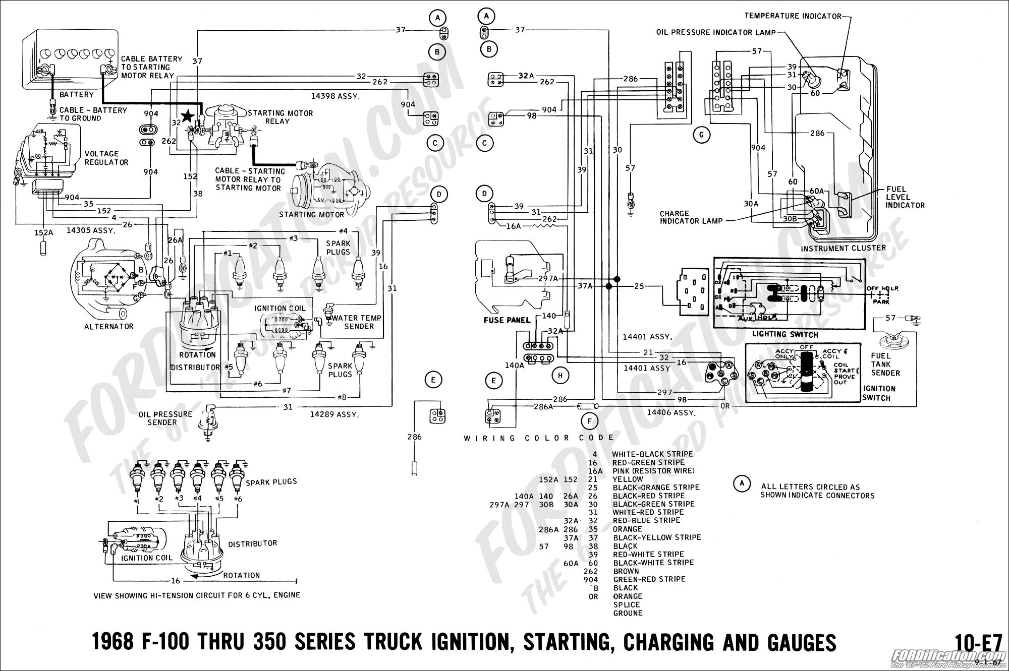
Pretty sure this won't help but it might for reference as it's the closest thing we'll have here to an actual wiring diagramon the starter.
Jeff
http://www.fordification.com/forum/view ... 22&t=46251
SOLD-71 F-350 dually flatbed, 302 / .030 over V-8 with a "baby"C-6, B & M truckshifter, Dana70/4.11 ratio, intermittent wipers, tilt steering, full LED lighting on the flat bed, and no stereo yet (this way I can hear the rattles to diagnose)! SOLD!
Many Ford bumps / one 76' EB / and several dents through the years.
A lot of "oddball" Ford parts collected from working on them for 34 years now!
2008 Ford Escape 4 x 4
-
- New Member
- Posts: 63
- Joined: Thu Mar 12, 2015 2:36 am
Re: Starter rebuild help / unknown wire
Yeah the meds control the tremor pretty good, but I lost my fine dexterity & balance. I know how the back surgeries go. My body likes to make me feel older then I am. So I just take things at my own pace. I hope things get better for you!
Fortunetly I don't need need the starter right away. It was the core from the last time I replaced it. The core was only $7 bucks so I decided to rebuild it with a US made kit due to the low quality of the parts store rebuilt starters. This is my 3rd starter in 4 years. Usaly the bendix drive on the parts store starters tend to blow up into pieces. The sintered gear is poorly made. Which is how the wire broke. Little bits of the gear made it to the rear of the starter, and broke the wire as it got thrown about inside.
Worst case if no one knows ware this wire goes. I will just put it on the shelf with the wire disconnected, and a note so I don't forget. When my current starter fails I will examine it to find out, or just use the rebuild kit on which ever starter is in better condition.
I do the same with my alternator. $5 dollar core charge. So a good quality rebuild kit makes a better alternator. Victory lap makes all there stuff here in the US. I tend to run thier starter solenoid & voltage regulator for this same reason. I got tired of replacing the pos units from the parts store.
If anyone decides to take this on, and doesn't have a serious soldering iron here's a quick tip for taking care of the positive side brushes. Take a propane torch, and turn the gas valve down nice & low. With the starter body disassembled & standing on end with the windows upwards. Just lightly touch the flame to the very top of the connection through the window. You won't really see the flame touch it if you do it right. In just a few moments the old solder will flow, and the old brushes can be removed. Installation is the reverse, but after adding a little heat put some small pieces of solder on top of the connection, and add a little heat. The solder will wick into the connection.
If you need to replace the battery stud like I did. They are available on ebay for a few bucks. Same strategy. Heat the stud from the outside until the solder flows, and pry the connection away enough to wiggle the stud out with a pair of needle nose pliers. Pretty easy to do, and as long as the flame only hits the very edge of the stud, or brush connection you won't set your starter on fire. If you do, blow it out. Haha. Happened only once to me because there was still a spot of grease soaked with kerosene on the outside. I had used kerosene to clean up the outside.
-
- New Member
- Posts: 78
- Joined: Sat Jun 27, 2020 12:37 am
Re: Starter rebuild help / unknown wire
I used to rebuild starters back in the 70s to 90s, mostly volkswagen/volvo/bosch, plus some american. If you don't have parts like bushings or can't find brushes easily rebuilding can become a drag. I just rebuilt a FE starter about three weeks ago. Required making a new bronze bushing on the lathe as it had an oblong worn hole which allowed the rotor to bind inside from the torque of cranking a freshly rebuilt engine. Guess I am in that 5% that rebuilds.
I cannot tell exactly from the photo as it is a bit dark. Here is what I remember.
There are two brushes mounted horizontally which connect to the housing (ground). The lower brush connects to the stator. The upper brush connects to the fixed contact from the solenoid on top. I seem to remember that to get the solenoid to close you need to apply +12V on the starter post and that goes through the solenoid coil back to ground. I think the thin wire centered under the solenoid has a nut or ring on the end that connects at the same bolt as one of the side brushes, to the housing (shown in the photo). If the wire is not connected to the housing (ground) the solenoid will not pull in and provide power to spin the starter. There may be another wire coming from the other end of the solenoid which goes to the large +12V post. In a nut shell, you should be able to measure a low resistance between the starter +12V post and the little wire that goes to the housing (ground). If you wre to put a couple of amps of 12V across the post and the little wire, you would see the solenoid getting pulled in.
Is the wire in the foreground the one in question?
You do not have the required permissions to view the files attached to this post.
-
- New Member
- Posts: 78
- Joined: Sat Jun 27, 2020 12:37 am
Re: Starter rebuild help / unknown wire
Hopefully another helpful hint...
Once you put the starter together leave off the cover for the solenoid and the cover ring that covers the openings at the rear of the starter. Tape a heavy piece of cardboard across the fixed contact on the solenoid to prevent the moving contact from providing power to the starter. By doing this, you can test out the solenoid operation/wiring by touching a +12V power/jumper cable to the starter (ground connected to the housing) while it is sitting on the ground or on a bench. The solenoid should close with a snap and the drive gear should move to the extreme out position. The starter will not spin. When you test this way, you are able to avoid the tendency for the starter to jump from the torque of start up and the huge spark from touching the +12V battery post with a jumper cable. You can also easily see the solenoid move and see how far the drive gear comes out. If this all looks ok, remove the cardboard insulator and finish putting the covers on the starter. You can now test but you need to find a way to hold the starter in place while it tries to jump when starting.
-
- New Member
- Posts: 63
- Joined: Thu Mar 12, 2015 2:36 am
Re: Starter rebuild help / unknown wire
Yes that is the wire, and figured it out. It does go under the nearest negative brush.
I found the patents for the starter. Which had a better illustration, wiring diagram, and semi helpful description. Finding a listing for a new contactor switch brought it all together, and clarified everything.
I had originally thought there were a total of 4 motive field coils. With the 4th having a parallel coil, or "shunt coil". I was partially correct. There's 3 motive field coils. The forth is the pull down coil, with a parallel weaker hold down coil in it.
How the picture of the new contactor switch helped. Fresh from the factory the negative brush nearest to the battery cable has a threaded junction block that screws to the frame. Then runs to the negative side of the contactor switch. Ware it is spot welded (not soldered) to the switch.
When they are rebuilt, or re-brushed the first time you are supposed to clip the brush off the junction block. Leaving just enough wire on the junction block to solder on the new brush in order to maintain originality. Rebuilding companies just use a slightly longer frame screw, and stack all 3 connections on the screw. Which is a PITA to do by the way. Lol one always wants to tighten to the frame first. Making it impossible to tighten the other. Some rebuilders will drill out the threads on the original junction block to prevent this. It would be faster & easier to just do it right the first time, and solder the new brush on.
Well if your in the 5%, I may end up in the 1%.
I think the insulation on the field coils are broken down, or far to oil soaked causing a short to frame (ground) in the solenoid coils. I prefer to do an insulation break down test with the starter apart. It's a little more reliable. Sometimes sparks just happen, and can be misleading.
With it apart make sure the positive brushes and hold down coil wire are not touch touching the frame. Use a piece of cardboard as you described to keep the contactor switch open. Then connect a jumper from the + battery post to the frame. Then attach the negative lead of a volt meter to the - battery post, and the positive lead to the battery post of the starter.
There should be no voltage. Don't rely on a ohm test. You need to check if the insulation fails with full battery current, not voltage. A ohm's test runs a a small amount of voltage, and nearly no current to check resistance. So it will check good if the insulation only fails when it draws full current.
It's a bit rainy today, so I will check tomarrow. If the insulation of the field coils fails I may rewrap & varnish the coils myself, or replace them if I can find someone with a new set in stock for reasonable price.
I still have plenty of 0.010 thick fish paper from back when I used to repair CRT monitors for resale. If I recall correctly these should be class B motors. So it's the perfect thickness. A roll of cotton wrapping tape is pretty cheap. The varnish isn't much either. I could even use a brush on scotch-kote. Which I use on the through bolts & other bits to prevent internal shorts. So the cost of field coils + shipping will need to be low for me to go the replacement route.
Thanks for everyone's reply. It helped focus my search to figure this out. I believe in learning to do stuff like this. It's fun, and one day a rebuilt unit may not be available, and shops that rebuild starters are few indeed. With the way the world is going, learning is even more important. It expands your knowledge beyond doing R&R's, which can save your bacon at an ever increasing rate.
- basketcase0302
- 100% FORDified!
- Posts: 6805
- Joined: Thu Jan 26, 2006 7:11 am
- Location: Hawthorne, Florida
Re: Starter rebuild help / unknown wire
Kudos to both you gentlemen, I've just never knew the resources existed (and got rid of my bearing press years ago when moving my shop 500+ miles).
69FE can you post a link to the vendor for the parts please?
Jeff
http://www.fordification.com/forum/view ... 22&t=46251
SOLD-71 F-350 dually flatbed, 302 / .030 over V-8 with a "baby"C-6, B & M truckshifter, Dana70/4.11 ratio, intermittent wipers, tilt steering, full LED lighting on the flat bed, and no stereo yet (this way I can hear the rattles to diagnose)! SOLD!
Many Ford bumps / one 76' EB / and several dents through the years.
A lot of "oddball" Ford parts collected from working on them for 34 years now!
2008 Ford Escape 4 x 4
http://www.fordification.com/forum/view ... 22&t=46251
SOLD-71 F-350 dually flatbed, 302 / .030 over V-8 with a "baby"C-6, B & M truckshifter, Dana70/4.11 ratio, intermittent wipers, tilt steering, full LED lighting on the flat bed, and no stereo yet (this way I can hear the rattles to diagnose)! SOLD!
Many Ford bumps / one 76' EB / and several dents through the years.
A lot of "oddball" Ford parts collected from working on them for 34 years now!
2008 Ford Escape 4 x 4